
Projects
Response Plan (Workflow) Engine
-
My conceptual idea, and subsequent design for a workflow engine in the PSIM solution came about as a requirement to perform several repeated actions on a device in response to a trigger. The specific test requirement was to turn a number of digital outs connected to LED's on and off 3 times. The digit out's were part of an ADAM 6050 box, however the design had to be flexible enough to allow any operation against any object in the system (the next use case being to move a PTZ camera between presets).
The concept and design came to me whilst on a train at Egham station, heading into London Waterloo and in true brainwave fashion was written on the back of an envelope. This was written in .Net 1.1 and predated the Workflow solution introduced by Microsoft in .Net 3.0 in 2005 by a couple of years giving a good USP to the product ahead of the competition.
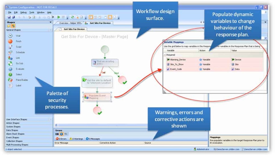
Each response plan (workflow) step object is very simple and with an interface of the usual Id, Label etc. and importantly a collection of Id's that keys off to the next step to be executed. The collection allows the step to perform conditional operations and to take a different route depending on the internal result when the step is executed. Having a collection also allowed the workflow engine to provide concurrent execution of steps within the same workflow, by providing a splitter step which would spawn off all the execution paths that would later all reconnect to one execution path by using a joining step.
To provide extensible calculations and logic I incorporated a scripting language that allowed for shapes to perform all the usual Math, logic, functions etc available in .Net and also for logical evaluation to be performed to provide logic branching in the step execution.
Over time the number of process steps grew to number almost 100 as the workflow became the key feature of the product covering alarm processing, as well as handling the processing of the UI.
In a manner similar to Visual Studio, the workflow (response plan) designer provided an analytical analysis of the user designed plans and would discover, and simulate execution of all the possible paths through the workflow and give a list of design errors and warnings. The error and warning panel also provided a link which if clicked would get the user to the UI that would allow them to correct the issue.